2024 © Allparts Equipment & Accessories. All Rights Reserved.
PP201 IGNITOR, HSI CYLINDER STYLE 2 WIRE 120
PP201 IGNITOR, HSI may have been used on World Marketing of America, Inc. kerosene and diesel portable forced air residential heaters and portable construction heater.
World Marketing of America Desa Models:
PK55
PK60
B50B
BV60S
B99
B110B
M140VT
R110A
RH125AT
RL125AT
R150E
R155A
REM110A
REM150D
REM155A
Need Help? Call us:
1-269-685-4123Related Items
The PP201 is a 120 Volt Hot Surfice Ignitor that was used by DESA International to start and ignite it's line of portable heaters that use the new circuit board style ignition systems.
The PP201 is the most current style Hot Surface Ignitor and is used to replace the all of the following Hot Surface Ignitors that were produced by Desa international, 102548-08 , 103068-03 ,HA1100 ,PP201-MP4.
Some of the models that use the PP201 / HA1100 kits were made by DESA International under the Reddy Heater, Master Heaters,John Deere, Remington, All-Pro, Universal, Husky by Home Depot, Kobalt by Lowes, Sears Craftsman, WW Grainger and Dayton brand names.
Desa, 102548-08 , 103068-03 ,HA1100 , PP201-MP4
This is a partial list and does not include all of the part numbers that may have been replaced by the PP201 Hot Surface ignitor
These parts were used in both High and Low pressure kerosene and diesel portable heaters manufactured by DESA International and private labeled for the following list of companies under some of the following brand names and sold at the following stores or retailers.
Sold at: Home Depot, Mennards, Lowes, Sears, Ace Hardware, Builders Square, Cosco, Sams Club, Walmart, WW Grainger, Portable Heater Parts, Master Distributors, Northern Hydraulics, NBMC, Sears, M & S Service Company Inc, FMConline, World Marketing and many other.
Sold as: Craftsman, Reddy heaters, Knipco, Dayton, Desa International, Master Portable heater, Universal Heaters, All-Pro, John Deere, Amoco, Koehring, Co-Op, Remington Kerosene and Diesel Heaters, Remington, Cenex, Heat Star and other private label names.
The following is service information for the PP201 Ignitor:
Note: It is important for the service technician to be cautious when working with the hot surface ignitor due to its extremely high operating temperature. Care should also be taken not to bend or strike the ignitor element.
The PP201 is a 120 Volt 60HZ Hot Surface Ignitor made in the USA, this part is triggered AC voltage being sent to the PP201 Hot Surface HSI by the two wire leads coming from the circuit board.
The hot surface ignitor is rated for 120 volts. With the rated voltage applied, the ignitor element heats up to 1400 Celsius (2550 Fahrenheit) within 5 seconds. The ignition system consists of an ignition control assembly Circuit Board and a HSI hot surface ignitor.
The ignition control assembly applies 120 volt power to the hot surface ignitor for 10 seconds which consists of a 5 second preheat period and a 3 to 4 second ignition run trial period. The extremely high temperature of the ignitor element ignites the fuel and air mixture within the combustion chamber. After the 10 second period the power is removed from the ignitor and the portable heater should remain running.
TEST PROCEDURE
Disconnect the two PP201 ignitor wires from Circuit Board ignition control assembly. With a Ohm Meter measure the resistance of the PP201 ignitor at the wire end terminals with an ohmmeter (use 0-200 OHM scale). The PP201 ignitor resistance should measure 30 to 175 OHMS. If resistance measures outside of this range, then the PP201 ignitor is defective and should be replaced.
The PP201 Ignitor can also be tested by applying 120 volts direct to the wire end terminals for no more that 5 seconds with a insulated safety test cord. If the PP201 igniter does not glow with 120 volts connected directly to the PP201 wire end terminals the PP201 HSI Hot Surface ignitor is defective and needs to be replaced.
Hot surface Ignitor Replacement Instructions
Removing Old Assembly
1. Using a 5/16 Nut Driver, remove the six upper shell screws and four side cover screws and remove the upper shell cover and side panel cover. (see Figure 1).
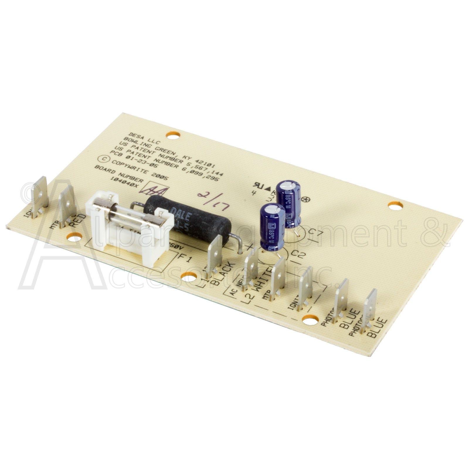
2. Carefully disconnect the two ignitor wires from ignition control circuit board assembly.
These wires may currently be yellow, orange, grey or purple on your unit, but they will all be replaced by the new ignitor using the 2 yellow wires.
It does not matter which yellow ignitor wire goes to the 2 ignitor labeled spades on the ignition control circuit board assembly. (see Figure 2).
3. Pull ignitor wires up through hole in lower shell.
4. Carefully disconnect rear fuel supply line hose and front air supply line hose from the nozzle adaptor. Use caution when removing these lines on units with a plastic adaptor, too much force will cause the plastic hose barbs on the nozzle adaptor to crack off.
The air supply line coming from the motor air pump goes to the rear hose barb connection on the nozzle adaptor connection.
The fuel supply line coming from the tank goes to the front hose barb on the nozzle adaptor connection.
Remove photocell from photocell bracket (see Figure 2).
5. Remove complete combustion chamber from the heater body.
Stand combustion chamber on end with nozzle adapter bracket on top (see Figure 3).
6. Remove ignitor screw with a 1/4 nut driver. Carefully remove ignitor from nozzle adapter bracket.
7. Carefully remove replacement ignitor from packing.
Do not touch the Black Ceramic end on the ignitor this may cause immediate damage to the ingitor or can greatly reduce the life of the newly installed ignitor.
8. Being extremely careful guide the new ignitor through the opening in nozzle adapter bracket and seat the ignitor into position.
Use caution not to strike ignitor element in any way.
Attach ignitor to nozzle adapter bracket screw that was removed during disassembly using a 1/4 nut driver. (see Figure 3).
Torque 8 to 15 in. lbs. Do not over torque or immediate damage may occur.
9. Carefully replace combustion chamber.
10. Route yellow ignitor wires back down through hole in lower shell and back to the ignition control circuit board assembly, connect the two yellow wires to ignition control circuit board assembly.
It does not matter which yellow ignitor wire goes to the 2 ignitor labeled spades on the ignition control circuit board assembly. (see Figure 2).
11. Using a 5/16 Nut Driver, reinstall side cover to heater using the four screws that were previously removed.
Tighten screws until snug. Do not over torque.
12. Route and connect fuel supply line hose and air supply line hose to nozzle adaptor hose barbs on the combustion chamber burner head. (see Figure 2).
13. Replace photocell in photocell bracket Wires are to be routed as shown in Figure 2.
14. Replace upper shell and reinstall 6 screws using 5/16 Nut Driver.


